

Written by Barkman Concrete Published on September 12th, 2021
PRE-CONSTRUCTION CHECKLIST
Before you start construction, take the time to complete the necessary planning and preparation. This process will keep your project running efficiently and will aid in completing a quality installation. Make sure to address the following:
SAFETY
Your safety program should address items such as personal protective equipment, maintaining safe slopes and excavations, fall protection, rigging and lifting, as well as any other relevant safety precautions.
ENGINEERING AND PERMITS
Obtain the necessary engineering design and permits for your project. The soils for foundation and wall backfill should be properly evaluated by a trained professional. Unsuitable soils should be removed and replaced as recommended.
Note: This installation guide is intended to supplement a detailed, site-specific wall design prepared by a Professional Engineer. The construction documents for your project supersedes any recommendations presented here.
REVIEW THE PROJECT PLANS
Take the time to review and understand the project plans and specifications. Make sure you understand the detailed design for the project before starting construction. A pre-construction meeting with the wall designer, construction inspector, wall contractor, and owner or representative is recommended. Don’t be afraid to ask questions.
CONSTRUCTION PLANNING
Develop a plan to coordinate construction activities (material delivery/storage, equipment access, etc.) on your site. Make sure your plan specifically addresses how to control surface water during construction.
UTILITY LOCATION
Make sure to have underground utilities located and marked on the ground before starting any construction. Call 8-1-1 or go online to call811.com to schedule utility marking for your
project site.
MATERIAL STAGING
Store retaining wall blocks in a location close to the proposed wall. Blocks should be kept clean and mud free. Blocks should also be stored in a location which will minimize the amount of handling on the project site. Store geogrid in a clean, dry location close to the proposed wall site. Keep the geogrid covered or in the shade until installation to avoid exposure to direct sunlight.
EQUIPMENT
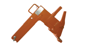
Make sure you have the proper equipment to handle retaining wall blocks and pallets on the construction site (Note: A specially designed Lifting Device is required for the installation of Outcropping blocks). Hand operated equipment used in wall construction should include shovels, rake, 2 ft (600 mm) level, 4 ft (1.2 m) level, broom, hammer, chisel, tape measure, string, spray paint, laser level, pry bar, concrete saw and a walk behind vibratory plate compactor capable of delivering a minimum of 2000 lb (9 kN) centrifugal force. Personal protective equipment should include appropriate clothing, steel toe boots, eye protection, respiratory protection, hard hat, gloves, hearing protection, fall protection, rigging, and other items as necessary to insure a safe working environment.
Note: On small or difficult to access sites, it is helpful to have two lifting devices. One for moving material from pallets to the site and another for setting blocks. This will allow for the material staging area to be located away from the construction space while providing safe and efficient access to the material in less than desirable site conditions.
BASIC RETAINING WALL
INSTALLATION NOTES FOR:
· Outcropping
· Belvedere
· Kodah
· Dimensional
Refer to product pages for specific information and details pertaining to individual products.
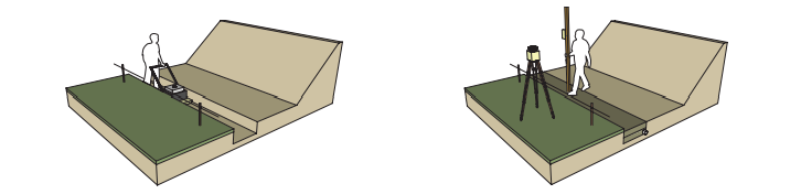
BASE PREPARATION
Proper base preparation is a critical element in the construction of your retaining wall. Not only is it important to provide a stable foundation for the wall, but a properly prepared base will greatly increase the speed and efficiency of your wall installation.
Proper base preparation starts with the subgrade soils (soils below the leveling pad). A typical wall requires excavation of at least 12 in (300 mm).This will provide 6 in (150 mm) for the leveling pad and 6 in (150 mm) of minimum bury of the blocks.
Note: excavation and bury depth will vary by product type and design. Please see project plans or product specific information for further information. Subgrade soils should be firm and capable of supporting the loads from the wall. At a minimum, all topsoil, organic, and other unsuitable soils should be removed from below the wall.
The minimum width of the leveling pad should be 18 in (465 mm) wider than the width of the block. This will provide 6 in (150 mm) in front of and 12 in (300 mm) behind the bottom block.
Note: for Outcropping and Grand Ledge Installation, you will need a wider leveling pad to ensure there is enough space for the depth of the blocks. The back cut behind the wall should taper and provide at least 18 in (465 mm) of space to ensure that the lifting device has enough clearance to be removed efficiently. When the back cut is too close to the back side of the wall, the device can get wedged and be hard to remove.
Once excavated, the subgrade soil should be compacted to a minimum of 95% maximum density as determined by a standard proctor test (ASTM D698). At this point the soil should be firm and free of topsoil, debris, roots, etc. Consult a soils engineer if in doubt. Any unsuitable material shall be excavated and replaced with compacted granular soils as directed by the engineer.

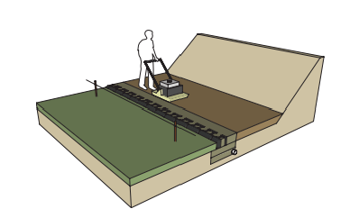
LEVELING PAD
Base preparation continues with proper leveling pad construction. An open-graded (free-draining) crushed stone leveling pad is typically used for retaining walls.
Walls can also be designed with a dense-graded crushed stone or concrete leveling pad. The choice of which type of
leveling pad to use is made by the wall designer and depends on several factors including the bearing capacity of the native soil, location of the drain outlet, conditions at the base of the wall, and any other special considerations for the wall.
The leveling pad material should be placed and compacted to provide a uniform, level foundation on which to construct the retaining wall. Proper elevation can be established with a laser level or transit. Check for level both parallel and perpendicular to the wall.
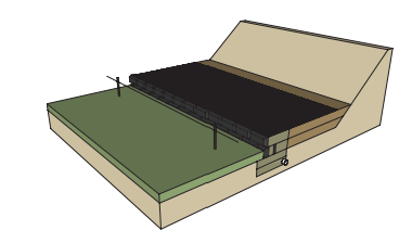
Place and compact leveling pad material as specified in the wall design. If crushed stone is used, place the stone in uniform loose lifts a maximum of 6 in (150 mm) thick. Lift sizes are relative to the size of the compactor being used. Compact the stone with a minimum of three passes with a 24 in (600mm) wide, walk-behind, vibrating plate compactor.
Note: Do NOT place a thin layer of sand between the leveling pad and bottom block. This layer will reduce the sliding resistance between the leveling pad and bottom block, as well as reduce the drainage capacity of the foundation stone.
DRAIN
A drain is installed in the lowest part of the open graded (free-draining) stone behind the retaining wall. If an open graded crushed stone leveling pad is used, the drain is installed on the bottom of the crushed stone leveling pad. If a dense graded crushed stone leveling pad is used, the drain is installed immediately on top of the dense graded stone.
Typically, a 4 in (100 mm) diameter perforated or slotted pipe (PVC or corrugated HDPE) is used. Daylight the drain pipe at the ends and/or through the face of the wall every 50 ft (15 m) to allow for drainage. The pipe can also outlet into a nearby drainage ditch or catch basin.
Because water can flow both ways through the drain pipe, connection to a catch basin or active storm sewer should only be made under the direction of a Professional Engineer.
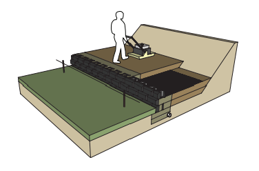
SETTING THE BOTTOM COURSE OF
BLOCKS
Proper placement of the bottom course of wall stones is critical in determining the overall appearance and integrity of the finished project. Take extra time on this step and the rest of the project will go smoothly. At this point you need to determine the best point of origin for the wall. If you have a fixed point, such as a building corner or a 90° corner, you will want to start the wall from that point and work your way out. This will minimize cutting of blocks. If there are no fixed points, start the wall at the lowest design elevation, as it is easier to step the base up than it is to step the base down.
Properly mark the location of the retaining wall. A string line or offset stakes are typically used to establish horizontal and vertical alignment. Review the Outcropping section for specific instructions on block alignment.
Where applicable, remove the bottom lip from the back edge of the blocks (applicable for Outcropping and Grand Ledge) with a hammer and chisel (bottom course of blocks only) so the blocks will lie flat on the leveling pad. Place a complete row of blocks on the prepared leveling pad. Blocks should be placed tight together.
Check all blocks for level from front to back and side to side as they are placed. Place and compact backfill in front of the bottom row of blocks to help hold them in place.
Compaction should be to 95% maximum density as determined by a standard proctor test (ASTM D698). Place open-graded crushed stone in the wedge-shaped gap between the blocks and at least 12 in (300 mm) behind the wall.
A stone meeting the gradation requirements of ASTM No. 57 with no material passing the No. 200 sieve is preferred. Place the stone in uniform loose lifts a maximum of 8 in (200 mm) thick.
Fully consolidate the stone. Carefully hand tamp the stone within 12 in (300 mm) of the blocks.
Place non-woven geotextile fabric between the drainstone and the remaining backfill material if specified. This prevents backfill material from migrating into, and clogging, the open-graded drainstone.
Backfill behind the drainstone with material as specified in the project design. Place the material in loose lifts as specified, but not to exceed 8 in (200 mm) maximum. Granular backfill shall be compacted to a minimum of 95% maximum density as determined by a standard proctor test (ASTM D698). Do not use any organic, topsoil, frozen, soft, wet, or loose soils when
backfilling the wall.
Re-check all units for level and alignment and sweep the top of each course of blocks clean before starting construction of the next course.
SETTING THE UPPER COURSES OF
BLOCKS
Placing the next course of blocks is similar to placing the first course.
Blocks should be placed to establish a running bond pattern (Dimensional Collections) or to follow an irregular pattern (Outcropping, Belvedere, and Claremont Collections).
Blocks should be installed with their sides pushed tight. Push blocks from Outcropping and Grand Ledge collections forward until the lip on the back of the block comes in full contact with the blocks below. Make sure that no stones get caught or wedged between the lip and the back of the blocks below.
Walls without the lip on the bottom (Belvedere, Dimensional, Kodah Freestanding, and Claremont Collections) should not be stacked exactly vertical. Instead, they should be setback as specified by each product line.
(Outcropping: Place a layer of non-woven geotextile fabric directly behind the blocks. This will keep materials from eroding through the small voids between the blocks.)
Place Geogrid reinforcing behind the wall as specified in the project documents. See geogrid installation information in the next section for further details.
Place and compact open-graded crushed stone between the blocks, and at least 12 in (300 mm) behind the wall following the procedure used for the bottom course of blocks.
Place non-woven geotextile fabric between the drainstone and the remaining backfill material if specified.
Place and compact backfill behind the drainstone following the procedure used for the bottom course of blocks.
Re-check all units for level and alignment and sweep the top of each course of blocks clean before starting construction of the next course.
Repeat these steps with each course of blocks to the top of the wall
GEOGRID INSTALLATION
Stability of reinforced soil walls rely on the interaction between geogrid reinforcement, soil in the reinforced zone, and the retaining wall blocks. It is very important that reinforced soil walls be constructed per the detailed design prepared by a Professional Engineer. Make sure you are using the proper type and strength of geogrid listed in the design. The geogrid layers need to be placed at the proper elevations and to the proper distances into the reinforced soil zone detailed in the design. It is also critical to use the appropriate backfill soil material in the reinforced soil zone.
Construct the wall up to the elevation of the geogrid layer shown in the design.
Place geogrid layers as shown in the project details extending into the reinforced soil zone to the design length.
Geogrid must be installed with the strong direction (roll direction) into the reinforced soil zone and not parallel to the wall. Geogrid must be placed in a continuous sheet throughout its length from the connection at the blocks to the back of the reinforced zone. Do not splice or overlap the geogrid.
For all retaining wall products except the Outcropping Collection, use the next layer of blocks to secure the front end of the geogrid (creating a friction connection). Make sure the geogrid is as close as possible to the front face of the wall without being visible. Pull the geogrid taut to eliminate any folds and pretension the geogrid. Pin or secure the back edge of the geogrid before placing the reinforced fill. Review the Outcropping section for specific instructions on geogrid and parawab strap installation
FINISHING THE TOP OF THE WALL
Completing a few simple tasks near the end of the project will ensure that the wall will function properly and look good for years to come.
Grade the top of the wall in such a way that surface water runs off away from the wall. Never leave the top of a wall graded where surface water will pond behind the wall, or saturate the backfill soils.
Place a layer of non-woven geotextile fabric over the top of the drainstone at the back of the wall. This will keep topsoil from migrating into the drainstone and causing problems.
If required, place the coping layer on the top of the wall. The coping blocks should be placed towards the front edge of the wall blocks and should sit securely on top without tipping forward under their own weight.
The coping layer should be carefully adhered with a concrete adhesive specifically formulated for segmental concrete block wall construction.
Note: With Outcropping and Grand Ledge, freestanding units can be used as capstones for applications where the top of wall is expected to be above the finished grade behind the wall. If the FS units are not available in your local market, Rosetta step units are also a great option.
MORE INFORMATION
Refer to product-specific Notes and Typical Construction Details for specific applications and construction practices such as chimney drain construction, fence installation, corner construction, drain placement, curve construction, and other details.
Typical allowable construction tolerance at the wall face is 1 in (25 mm) in 10 ft (3 m) (1:120) in the vertical and horizontal directions, and a rotation tolerance of 2° from wall batter.
Once you commence working, continue without interruption or delays. This will help expedite construction and minimize the time the excavation is open.
If at any time ground water seepage is observed along the exposed excavation behind the retaining wall, contact the wall designer immediately to determine the corrective action needed.
The construction site should be graded and maintained to direct surface water runoff away from the retaining wall throughout the entire construction process. If there is a rain event with surface water runoff producing erosion or scour near the retaining wall, contact the wall designer immediately to determine the corrective action needed.
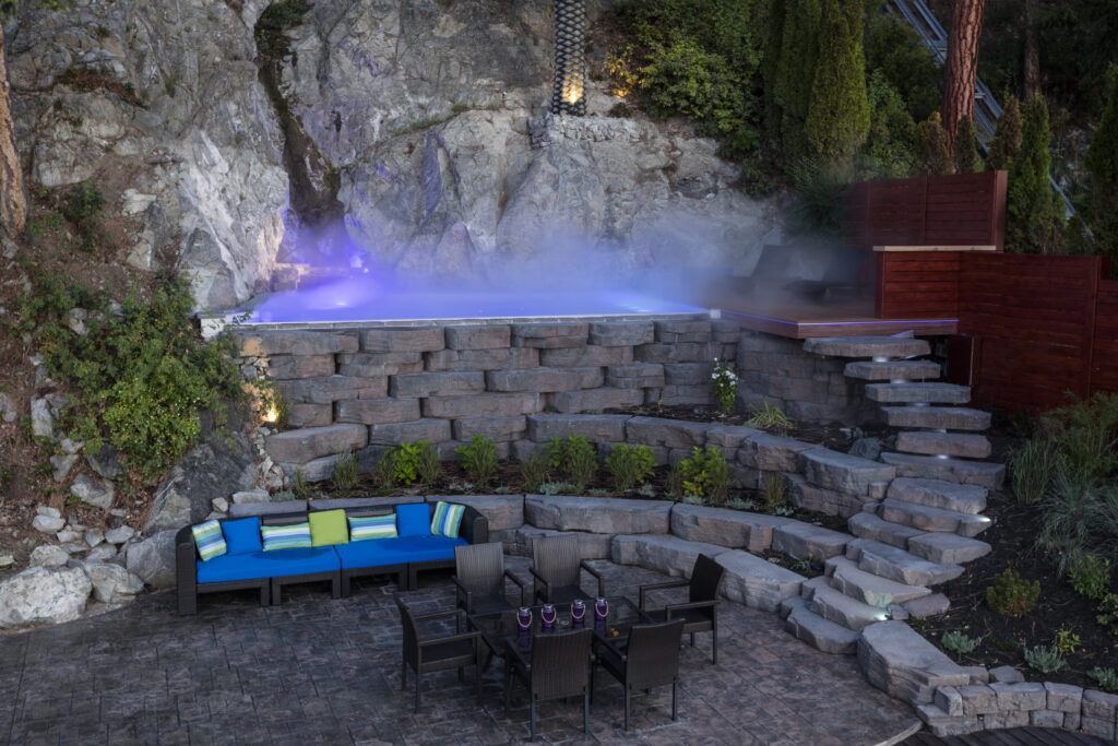
WATER APPLICATIONS
Due to the nature of wetcast concrete, the Rosetta Hardscape wall systems are well-suited for many shoreline and water applications. From small water features to custom ponds or where shoreline protection is needed, the wall systems can be implemented to provide the erosion control needed without
sacrificing the natural aesthetic of your project.
Refer to the typical design details for more information. Once you’ve gathered the necessary details of the project, site conditions, and any local building requirements, reach out to your local Rosetta representative for further details
ADDITIONAL INSTALLATION NOTES
FOR:
· Outcropping
Refer to product pages for specific information and details pertaining to individual products.
INSTALLATIONS REQUIRING GEOGRID
Please visit rosettahardscapes.com for detailed cross-sections of geogrid reinforced Outcropping walls. For Outcropping installations, do not overlap geogrid over top of blocks. Instead, run the geogrid directly up to the back of the blocks. In addition to this reinforcement, a Paraweb strap must be
installed through each lifting hook in the back of the Outcropping blocks. Please see standard details for Reinforced Outcropping Walls for further information.
Place and compact drainstone and reinforced fill following the procedure used to set the bottom and upper courses of blocks. It is important to place and compact stone and reinforced fill starting at the back of the retaining blocks and extending into the reinforced soil zone. This will help eliminate inbunching of the geogrid reinforcement.
Reinforced zone fill material is typically a sand or gravel with less than 5% infines in (material passing the No. 200 sieve). This material is usually classified as a GW, GP, SW, or SP. It is very important that you only use the fill material specified in your project design drawings and specifications.
Place retained soil immediately between the reinforced soil zone and the back of the excavation. Material should be placed in loose lifts of 6 in (150mm) maximum and compacted to 95% maximum density as determined by a standard proctor test (ASTM D698). Bring the reinforced and retained soil up to grade at the same time. At no time should the elevation of the reinforced soil be more than 1 block higher than the retained soil.
Tracked construction equipment should not be used directly on the geogrid. A minimum of 6 in (150 mm) of fill is required between tracked equipment and geogrid to prevent damage to the grid. Rubber – tired equipment may pass over the geogrid when traveling at low speeds of 5 mph (8 km/h) or less.
Avoid any sudden stopping or turning of construction equipment in the reinforced fill zone to prevent moving or damaging the geogrid layers.
Follow geogrid manufacturer’s requirements, including requirements for vertical separation and overlap of geogrid.
FOR ALL INSTALLATIONS
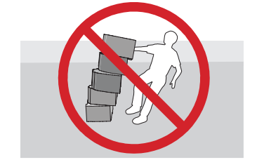
Never stack blocks more than one course above grade of backfill
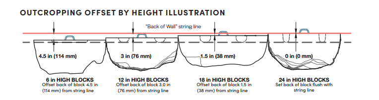
OUTCROPPING OFFSETS BY HEIGHT
OF BLOCK
One of the unique features of the Outcropping system is multiple block heights. To provide a uniform wall batter with multiple height blocks, the setback of the blocks varies proportionally with the block height. The setback in blocks is achieved with shear heels which are cast into the blocks. For a 6 in (152 mm) high block, the shear heels are 1.5 in (38 mm) deep (1/2 times 3 in (76 mm)). For a 12 in (305 mm) high block, the shear heels are 3 in (76 mm) deep (1 times 3 in (76 mm)). For an 18 in (457 mm) high block, the shear heels are 4.5 in (114 mm) deep (1-1/2 times 3 in (76 mm)). For a 24 in (610 mm) high block, the shear heels are 6 in (152 mm)
deep (2 times 3 in (76 mm)).
To ensure proper wall alignment and to account for the multiple height blocks and varying setbacks, you have to adjust the bottom row of blocks based on their height. Setup a traditional string line for the back of the wall, then offset the blocks per the detail at the bottom of this page.
Outcropping / Grand Ledge lifting device required for proper installation.